Heating model
This tutorial shows how ifctrano translates a hydronic heating system modelled in BIM into a trano model. The example
combines two federated IFC4 models of the same house: the architecture model ExampleHOM.ifc and a heating discipline
model sharing its project, site, building and storeys.
The heating model follows common IFC4 MEP practice: a gas condensing boiler (IfcBoiler), two heating circuits
(ground floor and first floor), each with a circulator (IfcPump), a three-way mixing valve (IfcValve, MIXING) and
a flow temperature sensor (IfcSensor), and eleven panel radiators (IfcSpaceHeater, RADIATOR) with thermostatic
radiator valves. Elements are connected with pipe segments and fittings through IfcDistributionPorts, grouped in
supply and return IfcDistributionSystems, and typed with the standard property sets
(Pset_SpaceHeaterTypeCommon.OutputCapacity, Pset_BoilerTypeWater.HeatOutput, Pset_PumpTypeCommon.FlowRateRange,
...).
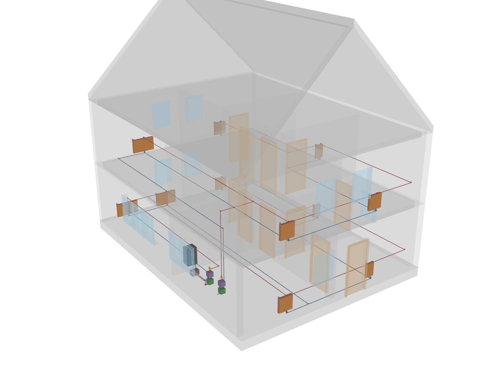
The heating network on its own, with supply pipes in red and return pipes in blue. The boiler, circulators (green) and mixing valves (purple) are in the kitchen; the radiators (orange) are placed in the rooms.
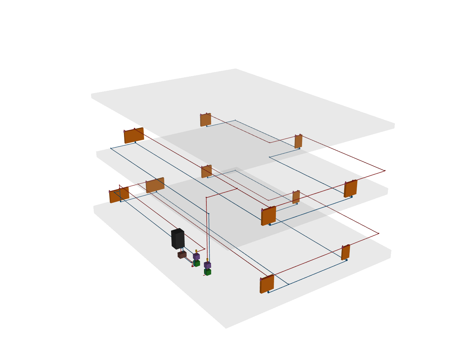
The heating model is generated by tests/hvac/example_hom_heating.py and can be written to a file with:
Generate the model
The heating model is passed next to the architecture model:
or with Python:
from pathlib import Path

from ifctrano.building import Building

building = Building.from_ifc(
    Path("ExampleHOM.ifc"), hvac_file_paths=[Path("ExampleHOM_heating.ifc")]
)
building.save_model(library="Buildings")
Heating elements contained in the architecture file itself are also taken into account, so single-file models work
without --hvac.
What ifctrano does
- Network: the port connections are turned into a directed graph. Pipes, fittings, isolating valves and sensors only carry connectivity; heat generators, circulators, mixing valves and radiators are the active components.
- Spaces: each radiator is assigned to the space it is referenced in (
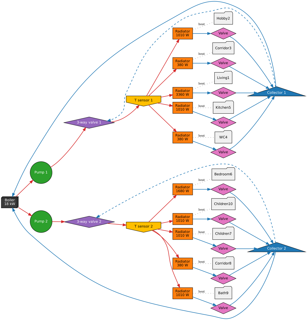
IfcRelReferencedInSpatialStructure, matched by GlobalId across the federated models) or, when the model has no such relation, to the space whose footprint contains it. - Circuits: radiators fed by the same heat generator through the same circulator and mixing valve form a circuit. Each circuit becomes trano's hydronic circuit: pump, three-way valve, temperature sensor, radiators with their valves, and a collector returning to the boiler.
- Parameters: the radiators of a space are lumped into one emitter whose nominal power is the sum of their
OutputCapacity(the living room has two 1680 W radiators). The boiler power comes fromHeatOutputand the pump nominal flow and head fromFlowRateRangeandFlowResistanceRange.
The resulting hydronic model, as generated by trano, is shown below. Supply connections are in red, return connections in blue, and the dashed lines are the bypasses of the three-way valves.
The same information is available in the configuration generated by ifctrano config ExampleHOM.ifc --hvac
ExampleHOM_heating.ifc. Each heated space gets its emission:
spaces:
- id: space_living1_v3g
  emissions:
  - radiator:
      id: radiator_space_living1_v3g
      parameters:
        nominal_heating_power_positive_for_heating: 3360.0
  - valve:
      id: valve_space_living1_v3g
      control:
        emission_control:
          id: emission_control_space_living1_v3g
and the boiler and circuits are described in the systems section (ground floor circuit shown):
systems:
- boiler:
    id: boiler_1
    variant: without_storage
    control:
      boiler_control:
        id: boiler_control_boiler_1
    parameters:
      nominal_heating_power: 18000.0
    inlets:
    - split_valve_1
    - split_valve_2
- pump:
    id: pump_1
    control:
      collector_control:
        id: collector_control_pump_1
    parameters:
      dp_nominal: 40000.0
      m_flow_nominal: 0.25
    inlets:
    - boiler_1
- three_way_valve:
    id: three_way_valve_1
    control:
      three_way_valve_control:
        id: three_way_valve_control_1
    inlets:
    - split_valve_1
    - pump_1
    outlets:
    - temperature_sensor_1
- temperature_sensor:
    id: temperature_sensor_1
    outlets:
    - radiator_space_corridor3_n2a
    - radiator_space_hobby2_uxa
    - radiator_space_kitchen5_dsw
    - radiator_space_living1_v3g
    - radiator_space_wc4_pwg
- split_valve:
    id: split_valve_1
    inlets:
    - valve_space_corridor3_n2a
    - valve_space_hobby2_uxa
    - valve_space_kitchen5_dsw
    - valve_space_living1_v3g
    - valve_space_wc4_pwg
    outlets:
    - boiler_1
Results
The model simulated for the first ten days of January in Uccle (trano's default weather), with trano's default controls: the rooms are heated to 21 °C from 7:00 to 19:00 and to 15.85 °C at night (see Control). The second panel shows the heat delivered by all the radiators.
Days 3 to 10 of the year (the first 2 simulated days are a warm-up and are left out).
| Case | Zone | Mean [°C] | Minimum [°C] | Maximum [°C] | Radiator heat [kWh] | Peak radiator heat [kW] | Heat from the generator [kWh] | Gas [kWh] |
|---|---|---|---|---|---|---|---|---|
| Gas boiler | Att | 13.0 | 9.1 | 18.3 | ||||
| Gas boiler | Bath9 | 19.6 | 15.4 | 25.6 | ||||
| Gas boiler | Bedroom6 | 19.1 | 15.4 | 21.7 | ||||
| Gas boiler | Children10 | 19.6 | 15.4 | 24.2 | ||||
| Gas boiler | Children7 | 18.6 | 14.9 | 21.4 | ||||
| Gas boiler | Corridor3 | 19.7 | 16.3 | 21.7 | ||||
| Gas boiler | Corridor8 | 20.0 | 16.5 | 22.3 | ||||
| Gas boiler | Hobby2 | 18.9 | 15.5 | 21.4 | ||||
| Gas boiler | Kitchen5 | 18.8 | 15.1 | 24.2 | ||||
| Gas boiler | Living1 | 18.6 | 15.0 | 21.8 | ||||
| Gas boiler | Wc4 | 18.9 | 15.5 | 21.7 | ||||
| Gas boiler | Mean of the zones | 18.6 | 15.2 | 21.8 | 125 | 4.4 | 148 | 190 |
What to expect. The heated rooms follow the schedule of their emission control: they are brought to about 21 °C during the day and cool down towards the 15.85 °C setback at night. The radiators deliver most of their heat when the set point switches back to 21 °C in the morning. The attic has no radiator and floats.
What the simulation shows. Over days 3 to 10, the heated rooms average 18.6 to 20 °C, between their day set point and their night setback; their minima (15 to 16.5 °C) are the night setback and their maxima (21.4 to 22.3 °C) the day set point, with sunny rooms going above it (up to about 25 °C in the bathroom, kitchen and children's room 10, which have south windows). The unheated attic averages 13 °C. The radiators deliver 125 kWh over the eight days, with a peak of 4.4 kW (hourly mean) when the rooms are heated up after the night setback (see the control example). The boiler produces 148 kWh, so about 23 kWh are lost in the distribution circuits, and burns 190 kWh of natural gas (lower heating value): a seasonal efficiency of about 78 %.
Difference with earlier versions. With trano 0.39 (ifctrano 0.15), the rooms were heated to 23.85 °C during the day, the model read the Chicago weather file, and the boiler kept its water hot day and night with a casing loss that trano 0.42 corrected. trano 0.42 heats to 21 °C, reads the Uccle weather and fires the boiler on demand, so the heat demand and the gas use are lower than they were.
Incomplete models
Real models often lack part of this information. ifctrano keeps going and records every assumption, which is logged
and available in building.heating.assumptions:
- Flow directions: exporters draw some pipes against the flow. ifctrano follows the modelled direction where it can, crosses wrongly drawn segments when it must (as few as possible), and only accepts a route from the heat generator to a radiator through a circulator, since no flow reaches a radiator otherwise.
- Sizing: when radiators have no
OutputCapacity, each space's emitter is sized for the design heat load of the space, computed with a simplified EN 12831-1 method from its external boundaries (transmission through walls, roofs, windows, and floors on ground) and its ventilation. Pumps withoutFlowRateRangeget the flow carrying the power of the radiators they serve between the design supply and return temperatures, and the boiler power defaults to the sum of the radiators it serves. - Heat generators: neither IFC4 nor IFC4.3 has a heat-pump class. Heat pumps exported as
IfcUnitaryEquipmentare recognised fromObjectType="HEATPUMP", their (type) name, model label or classification; otherwise they are modelled as a boiler. Their kind can also be given explicitly. - Unconnected radiators become ideal emitters, and a circuit without its own circulator or mixing valve gets the default ones of trano's circuit template.
The design conditions and the kind of heat generator are set with HeatingOptions:
from pathlib import Path

from ifctrano.building import Building
from ifctrano.hvac import DesignConditions, HeatingOptions, ProductionKind

building = Building.from_ifc(
    Path("architecture.ifc"),
    hvac_file_paths=[Path("heating.ifc")],
    heating_options=HeatingOptions(
        heat_generator=ProductionKind.water_water_heat_pump,
        design=DesignConditions(outdoor_temperature=-12.0, supply_temperature=45.0, return_temperature=35.0),
    ),
)
or, for the kind of heat generator, from the command line:
The figures of this page are generated by docs_src/heating_figures.py.